Ultrasonic Distance Measurement Using raspberry pi
Componant :-
HC-SR04
1kΩ Resistor
2kΩ Resistor
Jumper Wires
Ultrasonic Distance Sensors :-
Sound consists of oscillating waves through a medium (such as air) with the pitch being determined by the closeness of those waves to each other, defined as the frequency. Only some of the sound spectrum (the range of sound wave frequencies) is audible to the human ear, defined as the “Acoustic” range. Very low frequency sound below Acoustic is defined as “Infrasound”, with high frequency sounds above, called “Ultrasound”. Ultrasonic sensors are designed to sense object proximity or range using ultrasound reflection, similar to radar, to calculate the time it takes to reflect ultrasound waves between the sensor and a solid object. Ultrasound is mainly used because it’s inaudible to the human ear and is relatively accurate within short distances. You could of course use Acoustic sound for this purpose, but you would have a noisy robot, beeping every few seconds. . . .
A basic ultrasonic sensor consists of one or more ultrasonic transmitters (basically speakers), a receiver, and a control circuit. The transmitters emit a high frequency ultrasonic sound, which bounce off any nearby solid objects. Some of that ultrasonic noise is reflected and detected by the receiver on the sensor. That return signal is then processed by the control circuit to calculate the time difference between the signal being transmitted and received. This time can subsequently be used, along with some clever math, to calculate the distance between the sensor and the reflecting object.

The HC-SR04 Ultrasonic sensor we’ll be using in this tutorial for the Raspberry Pi has four pins: ground (GND), Echo Pulse Output (ECHO), Trigger Pulse Input (TRIG), and 5V Supply (Vcc). We power the module using Vcc, ground it using GND, and use our Raspberry Pi to send an input signal to TRIG, which triggers the sensor to send an ultrasonic pulse. The pulse waves bounce off any nearby objects and some are reflected back to the sensor. The sensor detects these return waves and measures the time between the trigger and returned pulse, and then sends a 5V signal on the ECHO pin.
ECHO will be “low” (0V) until the sensor is triggered when it receives the echo pulse. Once a return pulse has been located ECHO is set “high” (5V) for the duration of that pulse. Pulse duration is the full time between the sensor outputting an ultrasonic pulse, and the return pulse being detected by the sensor receiver. Our Python script must therefore measure the pulse duration and then calculate distance from this.
IMPORTANT. The sensor output signal (ECHO) on the HC-SR04 is rated at 5V. However, the input pin on the Raspberry Pi GPIO is rated at 3.3V. Sending a 5V signal into that unprotected 3.3V input port could damage your GPIO pins, which is something we want to avoid! We’ll need to use a small voltage divider circuit, consisting of two resistors, to lower the sensor output voltage to something our Raspberry Pi can handle.
Voltage Dividers
A voltage divider consists of two resistors (R1 and R2) in series connected to an input voltage (Vin), which needs to be reduced to our output voltage (Vout). In our circuit, Vin will be ECHO, which needs to be decreased from 5V to our Vout of 3.3V.

The following circuit and simple equation can be applied to many applications where a voltage needs to be reduced. If you don’t want to learn the techy bit, just grab 1 x 1kΩ and 1 x 2kΩ resistor.

Without getting too deep into the math side, we only actually need to calculate one resistor value, as it’s the dividing ratio that’s important. We know our input voltage (5V), and our required output voltage (3.3V), and we can use any combination of resistors to achieve the reduction. I happen to have a bunch of extra 1kΩ resistors, so I decided to use one of these in the circuit as R1.
Plugging our values in, this would be the following:

So, we’ll use a 1kΩ for R1 and a 2kΩ resistor as R2!
The input pin on the module is called the “trigger” as it is used to trigger the sending of the ultrasonic pulse. Ideally it wants a 5V signal but it works just fine with a 3.3V signal from the GPIO. So I connected the trigger directly to Pin 16 (GPIO23) on my GPIO header.
You can use any GPIO pins you like on your RPi but you will need to note the references and amend your Python script accordingly.
 The
module’s output is called the “echo” and needs a bit more thought. The
output pin is low (0V) until the module has taken its distance
measurement. It then sets this pin high (+5V) for the same amount of
time that it took the pulse to return. So our script needs to measure
the time this pin stays high. The module uses a +5V level for a “high”
but this is too high for the inputs on the GPIO header which only like
3.3V. In order to ensure the Pi only gets hit with 3.3V we can use a
basic voltage divider. This is formed with two resistors.
The
module’s output is called the “echo” and needs a bit more thought. The
output pin is low (0V) until the module has taken its distance
measurement. It then sets this pin high (+5V) for the same amount of
time that it took the pulse to return. So our script needs to measure
the time this pin stays high. The module uses a +5V level for a “high”
but this is too high for the inputs on the GPIO header which only like
3.3V. In order to ensure the Pi only gets hit with 3.3V we can use a
basic voltage divider. This is formed with two resistors.
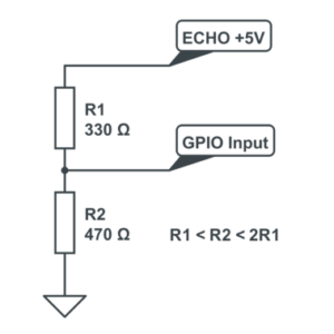
If R1 and R2 are the same then the voltage is split in half. This would give us 2.5V. If R2 is twice the value of R1 then we get 3.33V which is fine. So ideally you want R2 to be between R1 and R1 x 2. In my example circuit I used 330 and 470 ohm resistors. An alternative would be to use 1K and 1K5 values.
Here is a diagram of my final circuit. I chose GPIO23 and GPIO24 but you can use any of the 17 available GPIO pins on the GPIO header. Just remember to update the script.

HC-SR04
1kΩ Resistor
2kΩ Resistor
Jumper Wires
Ultrasonic Distance Sensors :-
Sound consists of oscillating waves through a medium (such as air) with the pitch being determined by the closeness of those waves to each other, defined as the frequency. Only some of the sound spectrum (the range of sound wave frequencies) is audible to the human ear, defined as the “Acoustic” range. Very low frequency sound below Acoustic is defined as “Infrasound”, with high frequency sounds above, called “Ultrasound”. Ultrasonic sensors are designed to sense object proximity or range using ultrasound reflection, similar to radar, to calculate the time it takes to reflect ultrasound waves between the sensor and a solid object. Ultrasound is mainly used because it’s inaudible to the human ear and is relatively accurate within short distances. You could of course use Acoustic sound for this purpose, but you would have a noisy robot, beeping every few seconds. . . .
A basic ultrasonic sensor consists of one or more ultrasonic transmitters (basically speakers), a receiver, and a control circuit. The transmitters emit a high frequency ultrasonic sound, which bounce off any nearby solid objects. Some of that ultrasonic noise is reflected and detected by the receiver on the sensor. That return signal is then processed by the control circuit to calculate the time difference between the signal being transmitted and received. This time can subsequently be used, along with some clever math, to calculate the distance between the sensor and the reflecting object.
The HC-SR04 Ultrasonic sensor we’ll be using in this tutorial for the Raspberry Pi has four pins: ground (GND), Echo Pulse Output (ECHO), Trigger Pulse Input (TRIG), and 5V Supply (Vcc). We power the module using Vcc, ground it using GND, and use our Raspberry Pi to send an input signal to TRIG, which triggers the sensor to send an ultrasonic pulse. The pulse waves bounce off any nearby objects and some are reflected back to the sensor. The sensor detects these return waves and measures the time between the trigger and returned pulse, and then sends a 5V signal on the ECHO pin.
ECHO will be “low” (0V) until the sensor is triggered when it receives the echo pulse. Once a return pulse has been located ECHO is set “high” (5V) for the duration of that pulse. Pulse duration is the full time between the sensor outputting an ultrasonic pulse, and the return pulse being detected by the sensor receiver. Our Python script must therefore measure the pulse duration and then calculate distance from this.
IMPORTANT. The sensor output signal (ECHO) on the HC-SR04 is rated at 5V. However, the input pin on the Raspberry Pi GPIO is rated at 3.3V. Sending a 5V signal into that unprotected 3.3V input port could damage your GPIO pins, which is something we want to avoid! We’ll need to use a small voltage divider circuit, consisting of two resistors, to lower the sensor output voltage to something our Raspberry Pi can handle.
Voltage Dividers
A voltage divider consists of two resistors (R1 and R2) in series connected to an input voltage (Vin), which needs to be reduced to our output voltage (Vout). In our circuit, Vin will be ECHO, which needs to be decreased from 5V to our Vout of 3.3V.
The following circuit and simple equation can be applied to many applications where a voltage needs to be reduced. If you don’t want to learn the techy bit, just grab 1 x 1kΩ and 1 x 2kΩ resistor.
Without getting too deep into the math side, we only actually need to calculate one resistor value, as it’s the dividing ratio that’s important. We know our input voltage (5V), and our required output voltage (3.3V), and we can use any combination of resistors to achieve the reduction. I happen to have a bunch of extra 1kΩ resistors, so I decided to use one of these in the circuit as R1.
Plugging our values in, this would be the following:
So, we’ll use a 1kΩ for R1 and a 2kΩ resistor as R2!
Connecting To The Pi
Powering the module is easy. Just connect the +5V and Ground pins to Pin 2 and Pin 6 on the Pi’s GPIO header.The input pin on the module is called the “trigger” as it is used to trigger the sending of the ultrasonic pulse. Ideally it wants a 5V signal but it works just fine with a 3.3V signal from the GPIO. So I connected the trigger directly to Pin 16 (GPIO23) on my GPIO header.
You can use any GPIO pins you like on your RPi but you will need to note the references and amend your Python script accordingly.
The
module’s output is called the “echo” and needs a bit more thought. The
output pin is low (0V) until the module has taken its distance
measurement. It then sets this pin high (+5V) for the same amount of
time that it took the pulse to return. So our script needs to measure
the time this pin stays high. The module uses a +5V level for a “high”
but this is too high for the inputs on the GPIO header which only like
3.3V. In order to ensure the Pi only gets hit with 3.3V we can use a
basic voltage divider. This is formed with two resistors.If R1 and R2 are the same then the voltage is split in half. This would give us 2.5V. If R2 is twice the value of R1 then we get 3.33V which is fine. So ideally you want R2 to be between R1 and R1 x 2. In my example circuit I used 330 and 470 ohm resistors. An alternative would be to use 1K and 1K5 values.
Here is a diagram of my final circuit. I chose GPIO23 and GPIO24 but you can use any of the 17 available GPIO pins on the GPIO header. Just remember to update the script.
Ultrasonic Module Circuit
Python Code :-
#!/usr/bin/python
#
# ultrasonic_distance.py
# Measure distance using an ultrasonic module
#
# Programmer :Onkar Dhandale

# Import required Python libraries
import time
import RPi.GPIO as GPIO

# Use BCM GPIO references
# instead of physical pin numbers
GPIO.setmode(GPIO.BCM)

# Define GPIO to use on Pi
GPIO_TRIGGER = 23
GPIO_ECHO = 24

print "Ultrasonic Measurement"

# Set pins as output and input
GPIO.setup(GPIO_TRIGGER,GPIO.OUT)  # Trigger
GPIO.setup(GPIO_ECHO,GPIO.IN)      # Echo

# Set trigger to False (Low)
GPIO.output(GPIO_TRIGGER, False)

# Allow module to settle
time.sleep(0.5)

# Send 10us pulse to trigger
GPIO.output(GPIO_TRIGGER, True)
time.sleep(0.00001)
GPIO.output(GPIO_TRIGGER, False)
start = time.time()
while GPIO.input(GPIO_ECHO)==0:
  start = time.time()

while GPIO.input(GPIO_ECHO)==1:
  stop = time.time()

# Calculate pulse length
elapsed = stop-start

# Distance pulse travelled in that time is time
# multiplied by the speed of sound (cm/s)
distance = elapsed * 34000

# That was the distance there and back so halve the value
distance = distance / 2

print "Distance : %.1f" % distance

# Reset GPIO settings
GPIO.cleanup()


I have been your silent reader for long.. Now I think you have to know how much your articles have inspired me to do better. This is very insightful and informative. Thank you for sharing. I would love to see more updates from you.
ReplyDeleteElcometer